FH VentLib Guides
Source löschen und Instanzen behalten
Im Dialog Delete Source Variant ist Delete all instances standardmäßig aus. Die abhängigen Instances bleiben als Achsen-Platzhalter mit unveränderten Transformationen, Profilen, Locks und Chain-Metadaten bestehen. Sobald dieselbe Source-Variante erneut generiert wird, verbindet VentLib diese Instances automatisch wieder. Aktiviere die Option nur, wenn auch alle abhängigen Instances entfernt werden sollen.
Locked Append und Trim
Bei rotationsgesperrten Teilen prüft New Append vorab, ob die gewählten Connector-Achsen einander gegenüberliegen. Eine falsche Anschlusskombination wird abgelehnt, bevor alte Chain-Beziehungen gelöst werden. Wähle in diesem Fall den anderen Connector. Re-fit nennt zusätzlich die blockierenden Location-/Rotation-Kanäle. Ein vollständig gesperrtes Folgeteil darf stehen bleiben, wenn der richtige Connector axial zum CUT ausgerichtet ist.
Fehlende Verbindungsteile
Die Chain Order darf eine geplante Reihenfolge auch dann speichern, wenn noch ein Verbindungsteil fehlt. Solche Nähte erscheinen als Work required: BFUI–SLU nennt beispielsweise ein passendes MFI, zwei weibliche Rohrenden nennen NPU oder NPUI, und unterschiedliche DN-Werte verlangen einen geeigneten Reduzierer/Adapter. New Append und Connect Chains erzeugen solche unvollständigen Direktverbindungen nicht.
Air-Circle inline fan
Choose Parts Generator → Fans → Generate Air-Circle to create the DN100 Source for BAUHAUS 23207127; use Create Instance to place it. The planning envelope uses 315 × 180 × 232 mm, Ø98 mm connections, mass 1.94 kg and airflow 190–270 m³/h at 18–30 W from the cited product-page evidence. Internal and undimensioned casing details are approximations. Automatic Append remains unavailable until insertion-stop dimensions are evidenced. Only the sourced DN100 SKU is offered.
Official retailer product page · Source and model notes. Verify current product data before use.
MF female sleeve
Choose Parts Generator → Couplings → MF, select a registered DN and click Generate MF. MF joins two male circular fittings of the same DN. Its A/B connector frames lie on the two open end faces; Append overlaps the fitting nipples into the sleeve. Part Configure changes DN only among registered rows. Verify current dimensions and availability through the linked manufacturer source.
MFI DN 160 project correction
MFI offers DN 160 instead of DN 150 for both Type 25 and Type 50. This is a project modelling decision for a suspected source printing error, not a manufacturer-confirmed revision. Verify the current manufacturer documentation before ordering or installation.
Planning Colors: An initial Fit Cut inherits the complete Planning Color profile, exact color and render mix of the replaced project Instance.
Trim and manual Cut LengthPrecision: VentLib stores and regenerates CUT lengths to 0.001 mm, matching Blender's six-decimal metre display depth. Decimal object names use p as the separator, for example CUT_SRI_250_50_L417p952. CUT fitting targets 0.001 mm; Chain validity retains a 0.025 mm float32 guard.
Discoverability: Cut Length remains visible for fixed catalog parts such as SLU. Trim is disabled there; hover the button to see why the selected family cannot be cut and which families support exact length fitting.
- Place a fresh stock
INST_…of SR, SRSS or SRI inside one tracked linear Chain Order. - Place the two neighbouring parts at their final project positions with compatible connectors on one axis.
- Select only the length part and click Trim. VentLib keeps both neighbours fixed, aligns the active length part and rebuilds it to the exact gap.
- Select the resulting
CUT_…and use the same button whenever the axial gap changes; VentLib then rebuilds that same Object in place.
Cut Length is contextual and appears below Append only for a fresh SRI/SR/SRSS Instance or an existing Cut. SLU and other fixed catalog parts are intentionally not cuttable. Neighbouring Solver Locks are unnecessary; neither neighbour moves. An off-axis or non-opposed gap is reported without changing the scene. If a new piece is not yet between two Chain members, enter Length (or scale local X), choose connector A/B as its fixed end and click Cut Entered Length. Each purchased stock product keeps one SOURCE. Cuts retain their stock reference for Configure and EK, but do not create additional SRC collections; exact seams, corrugations and connectors are baked without drivers. Separate SRSS pieces require NPU. Separate insulated SRI pieces require NPUI; SRI manual cutting deliberately refuses an over-3000-mm multi-piece result. BFUI and other male Isol fittings insert directly into SRI. MFI joins two Isol fittings. SLU is a silencer.
K39B work-planning record
Each generated component carries a project link to the access-controlled Werkplanung / Installation section in K39B-Build_Lüftung_Planung. That section contains only binding installation decisions, concise source-backed instructions and project evidence. Research and unresolved discussion remain outside the binding section.
Open installation-documentation completeness
Parts Generator is organized as Straights, Bends, Couplings, Silencers, Branches, Fans and Outlets. Each category is independently collapsible and initially closed. The collapsed Catalogs section below Generate SRC at 3D Cursor separates immutable links shipped by the current 2HE-Blender / MEP release from Custom Catalog Assets. Online entries can be shown or hidden. Custom names and links can be created, opened, edited and deleted and are saved with the current .blend scene. Current generator cards carry the appropriate manufacturer prefix, such as Lindab | or Air-Circle |.
NPUI connects two SRI ducts with the same DN and Type 25/50 insulation. Select the published Type and diameter under Couplings, then click Generate NPUI. A/B represent the SRI jacket stop planes. The manufacturer sheet publishes mass and an 8-10 mm stop range; VentLib uses its 9 mm midpoint while marking the visible insertion depth and outer-jacket width as drawing-derived.
This is the evolving operating guide for VentLib. Chapters are updated alongside the add-on so working details are captured when they are discovered.
1. Components
1.1 Create components
- Open the 3D Viewport sidebar and select FH VentLib.
- Expand Components.
- Select the family and published size preset.
- Use Component Configure for live size, angle or length changes supported by that family.
- Use Update Name when configuration changes must be committed to source, object, collection and instance names.
1.1a Catalog
Catalog is the human-facing product library. Add Part and Exchange Part create a missing canonical Source automatically and silently reuse it thereafter. CBC/CBE uses a Type selector plus dependent published d1/d2 dropdowns; changing d1 filters d2 to combinations present in the manufacturer table. VR exposes the six published DN sizes from 125 through 400 and generates the matching grille, plenum and circular connection.
1.1b Outlets and external-wall grilles
The Lindab VR entry bundles dated German and Global data sheets. Its image opens the Global sheet; Part Info provides both repository copies and both manufacturer URLs, so the German proof document remains directly available.
1.1c Catalogs
Catalog links are grouped separately from generators. Online 2HE entries are maintained with the add-on; Custom Catalog Assets are scene-local and editable by the user.
Question-mark buttons beside supported headings open this Guide at the exact topic. Blender controls the delay and lifetime of native hover tooltips globally; the add-on therefore provides the adjacent button as the reliable clickable target.
1.1d Source & Instances
This advanced section is collapsed by default. See / Hide Source temporarily isolates the canonical Source without moving Planning Instances. Commit Source Position and manual Instance creation remain available for exceptional source-editing workflows.
1.1e Stock
The quantity table counts project Instances and cut lengths while excluding Sources, warehouse objects and previews. Show Used Parts rebuilds a temporary Local View matrix with each used product variant exactly once, grouped by family. Native viewport labels show product identity and current quantity. Closing the matrix deletes only its preview Instances and restores the previous active object and selection.
1.2 Component Configure
The section is collapsed by default and appears directly below Solver. It operates on the selected editable VentLib source object.
A selected collection instance also opens the same canonical SRC parameter set. The panel names both the source and selected instance; parameter and metadata changes affect the shared source geometry while the placed instance transform remains independent.
The active part's currently available diameter, angle and length fields also appear directly below the Solver Location, Rotation and Size controls. Both locations edit the same source values; only the active OCL object responds when several rows are selected.
- SRSS exposes its configurable length.
- BUSS creation uses separate Angle and Diameter dropdowns followed by Create BUSS. Both dropdowns always expose their full published value set. If a newly selected value does not match the existing counterpart, that counterpart returns to Please select. The BUSS sheet lists DN250 for 30°, 45°, 60° and 90°, but not for 15°.
- BSLU is a fixed 90° bend silencer. Choose 50 or 100 mm insulation first; Diameter then exposes only the DNs published for that insulation. Configure keeps DN directly editable beside the published selector and reports the derived overall leg length l, outer diameter dy and mass.
- Branches and reducers expose their applicable main and branch diameters.
- Published dropdowns represent manufacturer-supported values; numeric controls may permit planning values outside those presets.
1.3 Metadata and references
Metadata can preserve manufacturer identity, source documents, product URLs, images, PDFs and additional project media. Keep manufacturer-proven values distinct from interpolated or planning-only geometry.
In Part Configure, click the part preview icon to open its registered manufacturer/product reference. The dedicated Planning Colors subsection is closed by default. New Instances use a 50% Render Mix between their planning color and source materials; changing the add-on default never overwrites a value already saved on an Instance.
1.4 SRC-Indie and scene organization
Validated VentLib package milestones are deployed to the separate LIVE copy after integration to main under the repository's scoped standing authorization. Send NO-LIVE during a task to skip only that deployment. A Blender restart may still be required when registered classes or properties changed.
VentLib keeps canonical library controls under 2HE_MEP / HVAC / Manufacturer / Product family. Each generated static variant has one canonical root inside its instanced SRC__… collection. Sources may be arranged visibly in the scene warehouse instead of overlapping at the World Origin.
- Placed
INST_…occurrences stay in the currently active project collection. Moving or reorganizing an occurrence does not relocate its catalog source. - Move a canonical source root normally with Blender G, then click Commit Source Position in the Source Warehouse box. VentLib transfers that translation delta into the SRC Collection Instance Offset, preserving every placed instance.
- The command supports translation only. It rejects Rotation or Scale drift instead of silently changing project instances.
- The scene contains a non-rendering SOURCE WAREHOUSE sign that records this rule beside the library objects.
- Generate creates and selects only the canonical
SRC_…object at World Origin; it does not create a placement. - Create Instance accepts one or several selected Sources. For every directly selected Source it first commits a pending Source translation, then creates one functional Collection Instance in the Scene Collection and applies the Scene-saved transform relative to that Source. Non-Source objects in the same selection are ignored.
- A selected Instance is sufficient for the single-part workflow because VentLib resolves its canonical Source. For batch creation, directly select the required Source objects. The new Instances are all selected afterward and the last-created Instance becomes active.
- The operation is driver-free: every occurrence remains linked to its canonical
SRC__…collection for shared geometry, while its placement transform stays independent. Existing Instances are not moved or duplicated. - The collapsed Instance Transform Defaults matrix stores the last used Location, Rotation and Scale in the Scene. Its initial values are L=(1,0,0), R=(0,0,0), S=(1,1,1).
- Creating an existing exact product does not duplicate it: VentLib reports Product exists already and selects its Source.
- New generation has one procedure for every family; it never creates a WORK definition. Legacy variable occurrences remain readable during the engine migration.
Multi-Source example: select three warehouse Sources, leave unrelated helpers selected if convenient, choose the desired New Instance Profile, and click Create Instance. VentLib creates exactly three placements. Each receives that profile and the relative L/R/S defaults measured from its own Source. Non-neutral profile codes remain visible as name suffixes such as __SUPPLY or __EXTRACT after file reloads and Source updates; changing a profile keeps stored Chain/Append references synchronized with the resulting Blender name.
2. Chat-driven new-part development
2.1 Manufacturer PDF + object image workflow
A new component can be initiated by supplying the manufacturer’s product PDF link and a representative product image in the development chat.
- Paste the direct manufacturer PDF or datasheet URL.
- Attach or link a clear product image.
- Name the product family and manufacturer if they are not obvious.
- State the first required sizes or variants, if particular ones matter immediately.
- State whether the task is repository-only or should complete the governed LIVE and Pages cycle.
The development agent should extract only manufacturer-supported dimensions and variants, clearly classify approximations, define connector frames, implement the component inside the canonical VentLib package, and preserve the source material with the component documentation.
2.2 Reusable chat instruction
2HE DO add this manufacturer component to FH VentLib.

Manufacturer:
Product / family:
Manufacturer PDF:
Product image:

Required first variants:
[enter sizes/angles, or “use the published table”]

Please:
- inspect the manufacturer sources;
- identify published dimensions, sizes, mass and constraints;
- implement parametric planning geometry without inventing manufacturer data;
- add VentLib connector frames;
- add Component Configure controls and metadata;
- add focused Blender 5.2 regression tests;
- update the VentLib Guides, DevLog, catalog and public Page;
- validate in a separate clean Blender process;
- deploy only to the governed FH__VentLib LIVE destination;
- verify the public documentation and LIVE file hashes.
Without operative 2HE DO or equivalent explicit LIVE/Pages authorization, development stops at the validated repository result.
2.3 Expected result
- Canonical generator and published-data representation
- Appropriate source, work-object and instance behavior
- Connector frames with meaningful A/B/C/D identifiers
- Component Configure controls
- Manufacturer PDF, image and product references
- Focused Blender regression coverage
- README, DevLog, Guides and catalog updates
- Governed LIVE and Pages verification when authorized
2.4 Update an existing component
Provide the existing VentLib family, the changed manufacturer PDF or page, a current product image when visual construction changed, and a precise description of the required correction. The development task must compare the new source with bundled evidence, preserve still-valid variants and metadata, update focused regressions, and revise the same Guide and DevLog milestone rather than creating a parallel implementation.
3. Connections and assembly
3.1 Connector mappings
VentLib components expose connector frames such as A, B, C and D. Select the moving component first, then Shift-select the target as active, and choose a mapping such as A → B.
Clicking A/B/C/D temporarily uses that connector and the 3D Cursor as the transform pivot. As soon as another object becomes active, VentLib returns the pivot to Active Element, so the gizmo appears at the newly active object's origin. The watcher exists only while a connector pivot is armed and then stops itself.
3.2 Tracked Append
Append stores the selected moving occurrence, the active target occurrence and both connector IDs as VentLib topology. The connection remains tracked even when Blender parenting is deliberately removed. To extend an existing Chain, select the loose part first and make the Chain endpoint active, then choose the connector pair. If the selected part already belongs to another Chain, New Append refuses the operation before changing links or poses. For an intentional transfer, Detach that part first, then Append it to the new target.
Add Part and Exchange Part share the remembered Part Type and published parameter values directly below their buttons. The PDF icon immediately before them opens the online manufacturer document for that selected Part Type. Add Part uses the active part's selected Append axis. If that connector is occupied, VentLib splits exactly that local connection and inserts the remembered part while the existing neighbour keeps its World pose. This also works at connector C of a branched TVU; the unrelated A/B branches do not need to form one linear Chain Order. With no selected local edge it inserts after the active linear Chain member, or at the 3D Cursor outside a Chain. Exchange Part replaces only the active occurrence: its exact World pose, Planning Color and Chain references remain, while both neighbours stay fixed. Existing product Sources are reused silently and repaired when their internal geometry no longer matches the selected parameters. The current Planning Color selection wins over stale stored profile metadata. An incompatible replacement is allowed as unfinished topology and may prevent solving until its connectors or surrounding parts are corrected. Exchange turns Chain Parenting off before replacement so stale constraints cannot move the assembly.
Align Connector Coordinate performs translation without creating or changing an Append. Keep the part to move active, choose connector A/B, select a reference Object Origin or VentLib connector, and enable the required Global X/Y/Z coordinates. Active only moves one part; Active + Following preserves the selected suffix shape; Selected VentLib parts applies one identical World delta to the explicitly selected parts while excluding the reference object. Rotation, Transform Orientation and Pivot remain unchanged. Complete P constraints are suspended and rebuilt around the move, and moved Solver Locks capture their new targets.
Every connector-pair button transfers only the selected inactive occurrence. VentLib first disables every previous tracked edge touching that part and remembers each disabled outgoing mapping on its former child. The remaining old-chain parts stay where they are. The selected occurrence then joins the active target's surviving chain, whose explicit chain identity and name remain authoritative.
The New Append operation snaps every free world-transform channel to the requested active connector while individually locked Location, Rotation, and Size channels remain unchanged. A fully locked part therefore transfers topologically but stays in place as a solve anchor. Transform Orientation and Pivot do not affect this World-matrix calculation. When the moving part belongs to a P-enabled Chain, VentLib temporarily removes those movement constraints before placement and rebuilds P consistently for the resulting Chains, preventing an old Child Of offset from pulling the part away again.
Connector frames represent assembly datums, not necessarily visible free faces. BSLU and SLU variants with integral Safe nipples use their insertion-stop shoulders, so an appended MFI female sleeve overlaps the male nipple. Large SLU variants with loose NPU connectors have no integral projection.
3.3 Connect complete chains
- Select the open endpoint of the complete chain that should move.
- Shift-select the open endpoint of the destination chain so it is active.
- Expand Chain and choose Join + Move or Join in Place.
- Confirm the merged Chain Order and read its status.
Both joins preserve the complete assemblies and internal connector mappings. The active chain keeps its explicit name. Join + Move requires a complete direct joint and moves the selected chain with one common rigid world transform. Join in Place changes only topology: all world transforms remain untouched, and the combined Chain status names any missing MFI/NPU/NPUI, reducer or remaining pose work.
VentLib automatically reverses either Chain Order when necessary. A one-part Chain has two open ports, so VentLib chooses the spatially nearest deterministic pair. Branched topology, an interior endpoint selection or failed final topology validation cancels the transaction and restores transforms, topology, names, orders, Append memory and planned gaps.
3.4 Parent and Append state
- Parented is blue while the active object has a Blender parent. Clicking it preserves the world transform and changes the control to Re-parent.
- Append On is blue while the active part has an outgoing VentLib relationship. Clicking it stores the last target and connector pair, removes that relationship and changes the control to normal Append Off. While off, the remembered relationship is inert: it does not move with its former target and is not part of a chain. Clicking Append Off performs Re-Append: it restores that remembered target and connector pair, snapping only channels which are not locked.
- When the same connected pair is selected, the compatible connector buttons remain available. Choosing one is a New Append, not Re-Append: it re-aligns the available channels and replaces the stored connector mapping directly.
- Parenting is optional transport behavior; Append is the authoritative VentLib topology.
3.5 Build a tracked chain
- Start at one intended endpoint.
- Connect one new component at a time.
- Avoid branches during the first linear Solver workflow.
- Inspect the chain after each connection.
- Confirm that component and connection counts increase as expected.
The Chains list sits directly above Chain Order and discovers separate tracked assemblies in the scene. Chain Order prefixes every part with the connector used toward the previous and following member, for example [A > B]. A terminal one-port part uses — on its open side. Invert Chain reverses positions 1…N and their connector direction while every part keeps its world transform; it does not require every part to own exactly two connectors. A spatial Chain is loose diagnostic does not disable inversion when the topology still has one unambiguous linear path; solve or reconnect it afterwards. The chain containing the active component is marked automatically; chain rows do not replace the active OCL. Use the pencil control to assign a persistent project-facing name.
Use the up/down controls on a part row to change its tracked assembly position. Order Edit preserves all staged world poses and lock state, then asks for a solve to align the new connector sequence. Obstacle rows have no manual order controls: VentLib continues to place them where their world-space influence falls along the chain.
A normal click on a Chain Order part row exclusively selects and activates exactly that occurrence. Whole-chain selection remains a separate explicit action, so selecting a single part never leaves hidden additive selection behind.
3.6 Chain Order operations
The blue P state means every ordered transition has a working movement constraint. If a partial legacy state is detected, P appears inactive; clicking it rebuilds the complete coupling without changing World transforms.
Deleting a connected part with Blender's normal object Delete clears its dangling tracked edge automatically. Each remaining side keeps its exact World transform and becomes a valid open Chain. Select one open endpoint, Shift-select the destination endpoint last, then use Join + Move or Join in Place.
- Solve From Active keeps the previous Chain Order member fixed and translates the active part plus every following suffix until their seams close. At position 1, the active part itself becomes the fixed beginning anchor and VentLib solves positions 2 through End. Existing rotations and the modeled Chain shape remain unchanged. If connector axes are not already opposed, VentLib names the seam that must first be rotated or reconnected.
- Cut Chain removes exactly the connection between the active member and its next Chain Order member. All world transforms remain unchanged; active P constraints are suspended before the split and rebuilt separately inside both resulting multi-part Chains. Both sides are therefore independent assemblies, and the removed connector pair remains available as dormant Append memory.
- Detach Part removes the active part from both adjacent tracked Appends and from VentLib Chain Parenting without deleting or moving it. Use the named Chain action or the X at the right end of that part's Chain Order row. Its World transform is preserved exactly; the remaining physical sides become separate Chains rather than being joined through the removed part.
- Invert Chain reverses only the operational order and connector directions. It accepts one-port terminal components and path-selected sides of multi-port fittings.
- Duplicate copies every part and rebuilds an independent Chain Order, tracked Appends, name, Parenting state and Missing Part records, offset 250 mm on X, Y and Z so the copy stays visible. Duplicate in Place deliberately creates the same independent copy at the original world poses.
The visible Chain Order is authoritative for all operations. Older scenes may store an Append edge in the opposite parent/child direction; that storage provenance does not change which side is previous, following, fixed or movable.
Branch fittings: main run and separate branch Chain
For TVU45, A, B and C are physical Safe insertion-stop planes rather than the free nipple edges. The generator reads Lindab's published l as the A-to-B stop spacing and l3 from the A datum along the 45° branch centreline to the C stop. The visible nipples continue beyond those connection planes and their raised rings are the insertion stops.
A fitting such as TVU has three connectors. Use A–B for the linear main run and C for the branch. VentLib can record all three connections and report the resulting topology, but Fit, Solve, Solver and ordered movement currently require one unbranched linear path.
- Build or retain the main Chain through TVU connectors A–B.
- On the active TVU, click C under Append axes. Choose the new Part Type and click Add Part; Add Part uses the selected open axis. If a part is already eyeballed into position instead, enable Append in Place and append its suitable connector to TVU C.
- Append it to TVU C to establish the exact connector pose, then use Detach Part on that first branch part. Detach removes the tracked edge but preserves both objects' exact World transforms.
- Continue appending outward from that first branch part. It is now the beginning of a separate linear Chain and its Fit, Solve and Chain Order tools remain available.
The visible TVU-to-branch seam is therefore intentional but untracked in this temporary workflow. If the C connection remains tracked, VentLib correctly reports a branch and disables operations that need an unambiguous Previous-to-Next order. Do not use Detach on the TVU itself, because that also removes its main-run relations.
Solve From Active: worked example
A completed assembly can still report Chain is loose after several separately staged sections are joined. In the example below, the remaining 0.392 mm error lies at the seam after INST_BFUI_45_250_50__OUTDOOR_AIR.001. The preceding 17 parts already have their intended poses; the BFUI and the two rows after it are the side the user permits to move.
- In Chain Order, click
INST_BFUI_45_250_50__OUTDOOR_AIR.001. It becomes the active row; the row immediately above it is the fixed predecessor. - Read the disabled/enabled action status before clicking. In this case it reports: Ready: translate active + 2 following part(s); recapture 1 moved Solver Lock(s).
- Click Solve From Active. VentLib first translates the active BFUI onto its predecessor, then translates
CUT_SRI_250_50_L233onto the BFUI, and finally translatesINST_BFUI_90_250_50__OUTDOOR_AIRonto that CUT. - Confirm that Chain status becomes valid and inspect the three affected rows. Their rotations and modeled shape remain unchanged. The CUT stays exactly 233 mm; Solve From Active does not consume or redistribute adjustable length.
The active row defines the start of the movable suffix; selection count does not. A Solver Lock inside that deliberately moved suffix is not treated as an immovable obstacle: its final World target is recaptured. Blender Transform Orientation does not affect the operation because all translations are calculated in World space. If any required connector axes are not already opposed, the action refuses before moving anything. Use Trim when an SRI, SR or SRSS length must change; use Solve Between Locks when fixed targets and available length freedoms should determine the solution.
3.7 Chain list controls, Parenting and protection
Each row in Chains controls one complete tracked Chain. The eye shows or hides all parts; the plain V enters or leaves Local View; clicking the shortened name opens its full editable name; P couples every following part to its predecessor; the lock protects the complete Chain; the selection arrow selects all parts; and Trash removes the tracked links while preserving the objects and their world transforms. The fixed icon before Trash shows the current Chain status: a check means ready, tools mark a known missing assembly part, and an error sign marks a loose or invalid Chain. Hover shows the live diagnosis; clicking the status icon opens the relevant Guide section. Selecting a connected part highlights its Chain row even when that part is also registered as a planning obstacle.
Local View stores the current viewport orientation before isolation. A second click on the same or another Chain's V leaves Local View and restores that exact view together with the prior selection and active object, including selection-locked Chain parts. Blender restores the surrounding objects as part of its Local View toggle.
P does not create a Blender parent hierarchy. VentLib uses marked Child Of constraints, so the Outliner remains flat. Switching P off removes only these constraints and preserves every current world pose. Parenting requires one valid linear Chain. Invert Chain and Order edits rebuild P in the new visible direction, so position 1 is always the transform root.
A gray P control guarantees that no VentLib Chain-Parent constraint remains active. When an older or partially edited scene contains only part of a former P coupling, VentLib first waits for Blender to evaluate the loaded Child Of matrices and then removes all remnants while preserving those evaluated World poses. Clicking a detected partial state also turns it fully off; click P again only when the complete current Chain Order should move together.
Chains uses Hide, selectable Name, pencil Edit, Local View, P, protection, Status and Delete. The active Chain is shown by its blue name. Chain Order uses Hide, selectable Name, pencil Edit, Up, Down, Lock, side-selection and Detach. The lock cycles through free, Solver anchor and complete Location/Rotation/ Scale lock. The selection arrow toggles between the clicked part plus all following children and the clicked part plus all preceding parents. The clicked part remains selected; select another object or press Alt+A to clear Blender selection. The X detaches the part from tracked Appends and Chain Parenting without moving or deleting it; its world pose stays unchanged. Selecting none retains the pinned Chain Order.
While the pointer is over the open Viewport sidebar, Up and Down select the previous or next Chain Order part. Navigation follows the complete order across pages and wraps from End to Start or Start to End. The mouse wheel remains available to scroll the complete VentLib panel.
The blue Chain lock prevents normal selection and Location, Rotation or Scale edits and disables VentLib Chain and Solver controls. Unlock remains available from the Chains list and restores any native object locks that existed before protection. Solver Lock is independent: it marks a world-space solver anchor and never disables ordinary G/R/S transforms.
Blender's native hover tooltips cannot be entered, kept open or contain interactive controls. A status hover gives a short preview; click the status icon for a persistent popup containing every current message and clickable Guide links. With 2HE Commands bridge 0.4.3 or newer, a matching open VentLib page is reused and navigated to that anchor. Without the bridge, VentLib opens the URL through the system browser.
Chains and Chain Order show at most ten rows and retain their page controls. Chain Order deliberately does not capture the mouse wheel, so scrolling continues through the complete VentLib sidebar even when the list passes beneath the pointer. Previous Part and Next Part step through the complete order and continue across page boundaries. Selecting a VentLib object in the viewport centers its Chain Order page with surrounding rows whenever the boundaries allow. Up and Down retain the global order.
Each valid Chain pose remembers its members' World rotations as the preferred starting articulation for later Solver solves. A successful solve updates the memory. Right-click a Chain Order name and choose Reset Remembered Rotation when that preference should be discarded.
Custom Catalog Assets, Obstacles, EK / Cut Stock and Files / Media use the same ten-row limit with compact first, previous, next and last controls. Planning Colors uses a dedicated picker with a text filter and ten visible rows. Its native list scrolls through up to 30 matching entries; page controls appear only above 30. The Template manager applies the same ten-row bound to its template and profile membership views.
Select several objects before choosing a profile to apply it to every selected VentLib occurrence. Selected objects outside VentLib are ignored and reported; their color, name and selection remain unchanged.
Hover, right-click Guide and persistent explanations
Every VentLib function and setting uses Blender's normal compact hover text. Right-click the same control to open Blender's native button menu. Its VentLib section gives a short explanation and * Open VentLib Guide, which navigates to the exact published heading. This replaces the separate Guide symbol and returns that space to action labels, Chain names and values. The plain ASCII asterisk is reserved for a future compact Guide mark if one is needed again.
Blender's native tooltip cannot remain open, accept pointer input or contain working links. Information and status rows are different: clicking those rows is their primary action and opens the persistent multiline explanation with its Guide action. A persistent window also opens when VentLib has inline paragraphs, an image or video to show.
Persistent explanations may contain paragraphs and several actions. Small
still images can appear in Blender. Video uses a preview and an explicit Open
action because Blender popups are not a dependable embedded movie player. The
browser bridge reuses an existing page under
http://2he.com/addons/FH__VentLib; it opens a new tab only if no
matching VentLib tab exists. All VentLib Guide URLs pass through this one
dispatcher; individual controls do not implement their own browser behavior.
Rich Guide windows provide an X control in their upper-right corner.
The bundled media proof shows a still image and an Open video action for a five-second MP4. The test excerpt comes from NASA Goddard's One Year On Earth, also published on YouTube; credit: NASA's Goddard Space Flight Center. The local excerpt is silent and is used only to verify the Guide media path.
The complete current control, tooltip, location and Guide-link inventory is
available in the complete Tooltip and Guide matrix and published with the add-on as docs/UI_HELP_MATRIX.md. A generic
VentLib right-click fallback covers newly introduced controls immediately;
specific headings are assigned in the same central registry.
Solver Lock
Solver Lock constrains VentLib solving on enabled World Location, Rotation and Length channels. Ordinary Blender G/R/S remains available. The Chain Order lock cycles through free, Solver anchor and complete native transform protection.
3.8 Align & Adjust
Align & Adjust turns a constraint into four physical choices:
C — Match Location / Rotation / Scale channels
D — Adjust using this part or length CUT
- Choose A and its Origin or VentLib connector. Choose any Blender object as B; ordinary objects use their World Origin, while VentLib parts may use Origin, connector A or connector B.
- Under C, turn on only the coordinates A should inherit. Under D, choose A itself for a direct move or choose an internal baked SRI/SR/SRSS CUT and enable Length. If B lies beyond A in the same Chain, B remains fixed and only the parts from CUT D through A move.
- Click Preview. Blue wire ghosts show the proposed moved parts and a short status sentence reports the movement and CUT. The original scene remains unchanged and Apply becomes available only after a valid Preview.
- Click Preview again to discard it, or click Apply to commit one Undo step. Apply turns Preview off but retains A/B/C/D for another run. Closing or reloading VentLib also removes an uncommitted Preview.
VentLib refuses references, channels or freedoms that cannot form one deterministic adjustment. Applying a CUT adjustment validates the rebuilt CUT seams and restores the original transforms and lock targets if fitting fails. Raw Blender Scale stays unavailable for VentLib parts; catalog size changes use an explicit Source-size variant instead.
4. Solver
4.1 Status, locks and repair
Solver reports topology and connector accuracy, persists per-component locks, and repairs disturbed linear chains from the active or locked anchor. The single Lock control shows the active component state: closed and depressed blue means locked; open with the default background means unlocked. Click it again to toggle the selected components.
VentLib locks constrain solver operations only and do not activate Blender-native transform locks. Two or more locks activate Solve Between Locks. That command solves every enabled World channel together: it may roll connector joints and resize eligible unlocked SR/SRSS straights, but it never chooses a locked side to move.
Chain Order entries are selectable. If the locked targets cannot describe one connected result, the persistent solve diagnostic explains the residual and available length reserve and links back to this Guide. Select the first part of the side that should move and use Solve From Active when the user, rather than the constraint solver, should choose that side. VentLib translates that part onto its predecessor, then closes every later seam through successive translation-only suffix moves. Rotations remain unchanged; a seam requiring rotation is rejected before anything moves. Blender Transform Orientation (Global, Local and the other viewport choices) does not affect this World-space calculation. If Chain Parenting is on, VentLib suspends its Child Of constraints during the transaction and reconstructs them at the solved World poses. Normal Trim does not move either neighbour and therefore does not require neighbour locks; only its explicit additionally-selected-side variant may align that selected side. A Complete Lock remains an absolute boundary for every operation that could otherwise move it. This is a temporary calculation; it does not create Blender parenting.
4.2 Solve and Live Solve
Full, Active and Span define only the part of the tracked Chain that is in scope. The adjacent Apply runs that scope; for Span, Check performs the same feasibility test without changing geometry. This scope choice is independent of the A/B/C route method.
Live Solve observes the actively moved component as the user-intent pivot and solves both chain sides independently. Untouched locked endpoints retain their captured world targets. An unreachable side remains separated at the pivot and reports the unresolved length instead of forcing an unstable transform.
Check Selected Span
This is a preview-only local RSA feasibility test. It answers whether the selected freedoms can close the bounded route before any geometry is changed.
- Uses one consecutive selection of movable bends and straight lengths.
- Holds the unselected neighbour on each side as a fixed connector frame.
- Ignores unrelated diagnostics elsewhere in the tracked Chain.
- Includes registered obstacles and the configured surface clearance.
- Reports the best remaining position and angle residual.
- Never applies a partial or infeasible result.
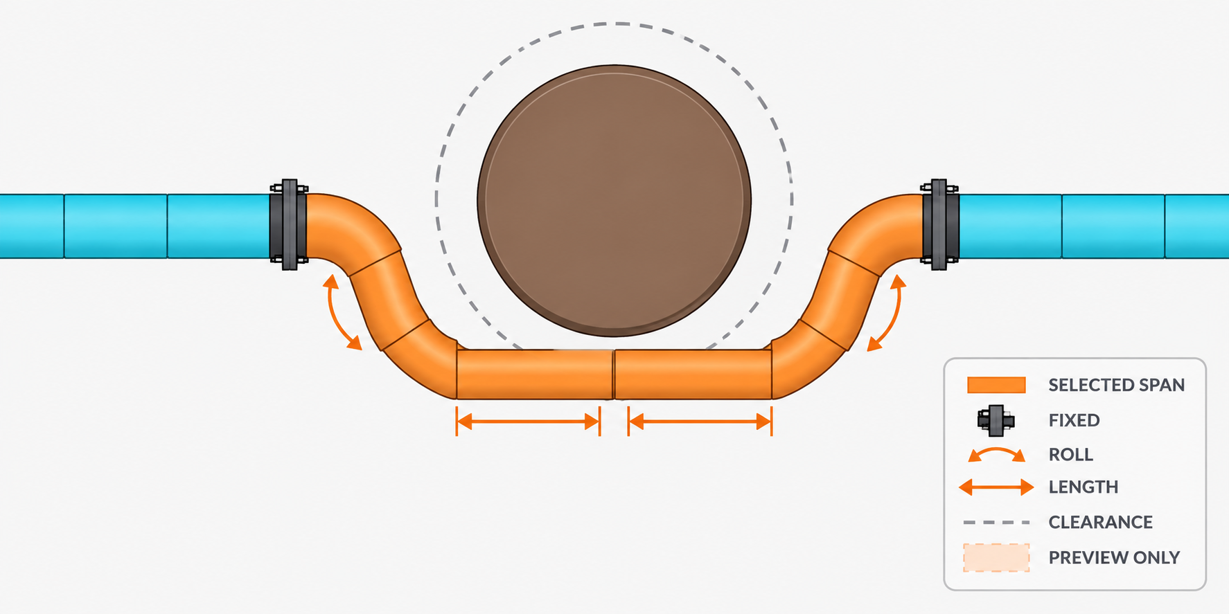
If the selected topology cannot close, continue in Route → A · Optimal. That layer may propose another catalog angle, exchange a part or add another bend. Review the new preview before Apply.
4.3 Variable SRSS length
Proportional On/Off controls whether eligible unlocked variable-length straights share required length changes. It defaults Off and remains visible but disabled when the active part is not an adjustable SR/SRSS straight. Each eligible straight can use its own remaining manufacturer capacity, so one saturated part no longer blocks available length in another.
4.4 Trim
Trim handles the first cut and every later re-fit. For an internal fresh stock Instance or baked CUT_ of SRI, SR or SRSS, place both neighbours at their intended final poses, select only the length part and use Append → Cut Length → Trim. Chain Order supplies both connector frames. VentLib keeps both neighbours and their Chain sides fixed, aligns the active length part to the previous connector and creates or regenerates exact unit-scale geometry to the following connector. Neighbour locks are not required.
A length part at the beginning or end of a Chain may have only one connected neighbour. In that case, select only the length part and click Trim: VentLib preserves the unconnected end's complete World position and orientation and shortens or extends the part toward the connected neighbour. World Location and Rotation solver locks on that endpoint are therefore compatible and remain enabled; Size Lock still blocks Trim. For an open CUT endpoint that should first connect to another movable VentLib endpoint, select that endpoint first and Shift-select the CUT so the CUT is active. This explicit two-object variant aligns and connects the selected side before fitting the gap. Connector types and axes must be compatible.
For a fresh Instance, VentLib creates its first baked Cut only after the complete result validates. For an existing Cut, the same Blender Object, collections, profile and topology remain intact. The selected length part must be unlocked. Off-axis or non-opposed neighbour connectors, ambiguous topology, missing Source, non-unit Scale or stock overlength cancel the entire transaction and restore geometry, metadata, names, references and World transforms without staged-object residue.
4.5 Aim for Straight Cut
Select the two open two-port endpoints of separate linear Chains and make the target side active. Choose Append → Aim for Straight Cut.... VentLib searches only the two endpoint roll axes and the lengths of the immediately adjacent SRI Cuts. A fixed adjacent MFI may be replaced by SRI after explicit confirmation.
The preview lists both roll angles, both adjacent lengths, the new middle SRI length and predicted residual. Apply rolls only the selected endpoints around their connected connector axes, preserves the far end of each adjusted straight, creates the middle Cut and joins both Chains. No other part moves. Locks, Chain protection, unavailable stock, impossible geometry or a result outside stock and Chain tolerances cancel the complete operation.
Use this for the common case where two staged bend ends are close but their open axes do not yet describe one straight line. Use Trim when the length part already sits inside one Chain, and Solve From Active when lengths and rotations must remain unchanged.
4.6 Curve Guide Fit
Choose a Bezier or Poly curve under Guide Fit (Prototype), keep both chain endpoints locked, and click Fit Chain to Guide. Additional internal locks divide the route into consecutive fitted spans. VentLib treats the curve as a soft centerline target while lock channels, connector geometry and SRSS limits remain authoritative. v0.22 samples the physical circular centerline arc of every BUSS/BUSS90 during refinement, so joint roll and unlocked SRSS lengths are judged against the route rather than connector points alone. The result reports RMS distance and is applied only when the complete chain validates.
When obstacles are enabled, v0.22.1 first plans a collision-free centerline, checks its catalog turn demand against the OCL bend capacity, and then permits refinement. Connector closure, every locked channel, obstacle clearance, monotone OCL progress and a physical centerline RMS of at most 40 mm must all pass. Otherwise VentLib restores every pose and SRSS length and requests an Order Edit or Missing Part.
5. Planned workflows
5.1 Missing Parts
VentLib reports missing bend and straight capacity at each Missing Part anchor. A new marker records the downstream connection at creation time and is retired automatically when a newly inserted component replaces that connection. After planning, Apply Catalog Route inserts the required BUSS90 occurrences, removes surplus BUSS45 angle capacity when necessary, adjusts unlocked SRSS lengths, and keeps the transaction only when all connectors, locks and obstacle clearances validate.
5.2 Guides and Obstacles
Registered obstacles are included in the OCL and may be enabled globally. Planning inflates them by pipe radius and installation clearance. Assembly refinement samples the true SRSS line and BUSS circular arcs against obstacle axes; an existing terminal may use one outward escape edge from a clearance envelope it already occupies, but later route segments cannot re-enter it.
Obstacle distance is the required free surface gap in millimetres, measured after subtracting both the routed duct radius and the obstacle body. It is a hard route constraint. The preview summary shows the target and the measured minimum; changing geometry requires a new preview, so panel redraw never runs an expensive solver.
If a method has a catalog-valid geometric solution but no collision-free alternative, VentLib keeps that solution as a red Preview and leaves Apply available. This lets the route and its clearance conflict be reviewed or deliberately accepted instead of replacing the result with a generic failure. Catalog-invalid geometry remains unavailable as A/B/C and can be inspected through Guide Influence.
Fit to Guide: choose the Start and End parts and name their actual connectors explicitly. Auto open remains available for an ordinary gap with one unambiguous open connector; A, B, C or D can address a branch connector such as TVU C directly. The endpoint connector frames, enabled obstacles, locks and the chosen freedom object form one immutable solve request. Selection state is not consulted again while the solver runs.
Start, End and Guide curve are Blender object references. They identify existing scene objects; they do not turn unused curve ends into infinite geometry. The Guide Curve remains in the scene as editable design intent after Preview and Apply, so its control points can be refined and the route solved again.
3D centerline treats the Bezier or Poly curve as the actual spatial thread along which VentLib ranks catalog-valid assemblies. All X, Y and Z coordinates participate. Drawing plane instead uses Top, Front or Side as the judged projection and interpolates the hidden coordinate between the physical endpoint heights. Set the preferred visible angle, symmetry, the length-freedom object and its permitted axis. VentLib evaluates analytic catalog families before using general path search.
A pick-point guide can be created without leaving the panel. Place the 3D cursor and choose Add Cursor Point for each desired corner. An existing Bezier or Poly Curve can also be assigned. Move a generated ROUTE_POINT_*, lock it and preview again to turn that visual edit into a hard constraint.
Route variants and preview
When Use Guide is enabled, the assigned curve participates in all three methods. A and B use it to rank valid alternatives, and C compares the preserved topology against it. Guide Influence separately exposes the guide-derived ideal geometry; it may deliberately reveal non-catalog turns or collisions and is never an applyable method. Editing the assigned curve marks A/B/C results for Update while preserving their previous comparison views.
Preview Existing Chain
This diagnostic reads the complete connected Chain containing the active part, keeps its two installed outer endpoint runs, and searches a collision-free rectilinear centerline between their inner connector frames. Registered obstacles, locked intermediate locations and the assigned Guide participate. It does not apply or replace parts. Use Route variant A when a catalog assembly with real preview parts is required.
Choose A, B, C or M with the method buttons. Each method keeps exactly one Recent Result, including its part count and arrangement. Selecting a letter is display-only: it shows that stored result without starting the solver. If none exists, use the explicit Update action. The Update row replaces only the selected A/B/C result; an enabled refresh icon means its inputs differ from the stored solve. M means Manual Aligning, stores a restorable object snapshot and updates only after another manual transform. The Status row uses ✓ for the applied result, * for another available Recent Result and - when none exists. A result remains applicable while its Update icon is enabled.
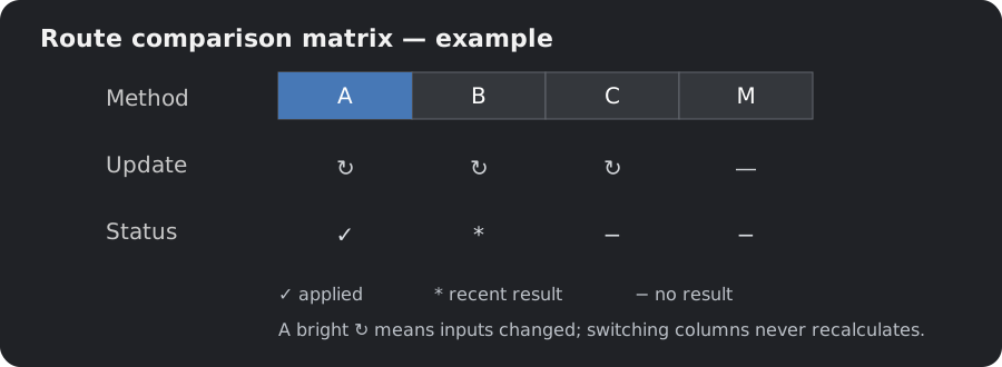
The A/B/C/M, Update and Status rows form one aligned four-column matrix. The Preview row below switches among the selected Route result, Existing Chain and Guide Influence. Only Route results can be applied. The half-width Apply button commits the result currently shown; Guide beside it opens this explanation. The other Recent Results remain available and become updateable when the installed scene changes.
- A/B/C solutions remain applicable despite clearance or obstacle warnings.
- Collisions remain marked red.
- The diagnosis retains the obstacle, affected part and measured deficit.
- Apply is disabled only when no usable geometry exists.
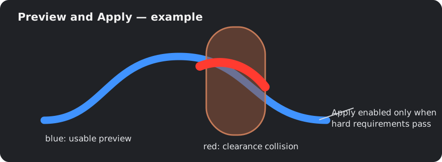
- A - Optimal: uses analytic geometry and the full configured catalog; declared Missing Part anchors may permit a parts exchange.
- B - Existing: accepts the geometry only when the current unlocked, diameter-compatible bends and straight capacity can build it.
- C - Conservative: keeps the tracked topology and holds the nominated length freedom at zero; released rotations and existing variable lengths remain available.
- Guide Influence: shows the ideal projected centerline and diagnoses collisions or non-catalog corners. It is a reference and cannot be applied as parts.
Symmetric layout
Symmetric layout is a ranking preference. When several routes satisfy the same endpoint, lock, catalog and obstacle constraints, VentLib prefers candidates whose first and last straight runs have similar lengths. This produces a visually balanced offset. The switch does not move parts by itself; it affects the next Preview.
Every preview stores its strategy, run lengths, bend demand, freedom movement, score and diagnostic. Apply refuses a diagnostic-only G result or a calculation that produced no usable geometry. Clearance and obstacle failures remain warnings on an otherwise usable A/B/C solution. A catalog-changing A result uses declared Missing Part anchors. B and C fit the existing tracked chain. During an existing-chain apply, VentLib removes Chain Parenting, rebuilds each variable-length part in a separate dependency-graph step, validates seams, locks and order, then restores Parenting at the accepted world poses. A rejected result restores the previous geometry and transforms.
A does not retain manual X scales on the existing CUT objects. It replaces the bounded span with the listed catalog assembly. B and C retain existing span objects where feasible; variable CUT lengths are rebuilt parametrically and finish at Blender Scale 1,1,1. The Preview summary identifies which policy is active. Exact per-object transform deltas are shown only after a strategy has actually solved them.
When a route uses a nonzero Length freedom before Start, the A preview also shows the future resized CUT and the moved objects through Start as blue wire ghosts. This keeps the proposed assembly visibly closed while the installed objects remain unchanged until Apply.
A route is rejected when bend construction lengths leave less than 100 mm of usable straight spool between adjacent fittings. Geometric closure alone is not sufficient: this quality gate prevents tiny filler fragments and visually restless four-bend detours from being labelled optimal.
Diagnostics and persistent detail
Each diagnostic is a clickable row. Hovering shows its complete message in the native tooltip. Clicking the row opens the persistent, word-wrapped information dialog; its Guide button navigates directly to this section. The triangle beside Diagnostics only expands or collapses the list.
For the TVU rolling-offset case, use TVU connector C as Start and the wall-entry SR connector as End. Nominate the upstream straight CUT as the length freedom, keep the wall-entry part fixed, register the crossing extract duct as an obstacle and use Top (XY) with a 45-degree preference. The connector roll remains a three-dimensional constraint even though the visible drawing is judged in plan.
If the TVU must keep its installed orientation, enable all three Solver Rotation locks on it and leave Allow branch roll off. The upstream straight may still change Length and move the connected TVU along that straight's axis; its other Location channels and all Rotation channels remain fixed. A locked rotation overrides an older preview and makes Apply refuse any stored branch roll.
The assigned Bezier curve remains in the scene as editable design intent after Preview or Apply. VentLib does not consume or delete it. When the exact curve crosses an obstacle or contains a non-catalog corner, G explains that conflict while A may approximate the desired form with catalog-valid runs, subject to endpoint, lock and catalog constraints. Clearance remains a visible, measurable warning that the user may accept.
If every two-bend family intersects an obstacle, A evaluates a five-run, four-bend family. All four turns remain published catalog angles; the five straight lengths are solved exactly. Roll candidates retain above, below, left and right escape directions. A terminal already touching the inflated clearance boundary may use one outward escape segment, while all following segments must remain collision-free.
The ten routing layers
Fit to Guide separates the task into ten layers. This makes every result explainable and lets a user change one design decision without silently weakening another.
| Layer | Meaning for the user |
|---|---|
| 1. Route contract | Name the exact Start and End connector IDs, diameter and system. These become the immutable request boundary. |
| 2. Topology | VentLib resolves Chain Order, branches and the bounded selected span before evaluating geometry. |
| 3. Freedoms and locks | Length, bend roll, permitted endpoint motion and locked world channels are explicit variables or hard constraints. |
| 4. Drawing plane and guide | Top, Front or Side defines the judged drawing. A Bezier or Poly curve supplies the desired centerline in that plane. |
| 5. Analytic catalog families | VentLib first solves clean symmetric arrangements from available straight and bend families instead of guessing poses. |
| 6. Clearance | Finite obstacle bodies are enlarged by both duct radii and installation clearance; violations stay red with obstacle, affected part and deficit, but do not suppress Apply. |
| 7. Parts synthesis | Every run and turn becomes a bill of actual catalog bends and cuttable straight lengths. |
| 8. Variants and ranking | A, B, C and G show optimal, existing-parts, conservative and ideal-guide interpretations for comparison. |
| 9. Visual intervention | The persistent Curve remains editable design intent. Moved and locked preview points become constraints for the next solve. |
| 10. Transactional apply | VentLib applies any usable chosen geometry transactionally. Missing geometry blocks Apply; clearance warnings may be accepted deliberately. |
The preview legend lists each straight run and each following catalog bend in route order. The guide curve is a design target: it controls the chosen projection while physical connector frames and catalog angles define buildable geometry; clearance remains diagnostic.
5.3 Inventory and Restock
Planned: distinguish unlimited stock, unavailable stock and required additional purchases. Restock quantities remain separate from components already available.
6. Validation and delivery
6.1 Validation
- Compile all add-on Python sources.
- Run focused Blender regressions in a separate factory-clean Blender 5.2 process.
- Run repository catalog tests and the Pages build.
- Do not hot-reload experimental RNA classes into the active production session.
6.2 LIVE deployment
The repository remains the source of truth. Blender loads only the expendable physical copy under the governed 2HE-Blender_Live root. A named LIVE request authorizes only that named add-on deployment.
6.3 Guide and Pages updates
Guides are living product documentation. Update the applicable chapter during each feature milestone, build the site, publish through the normal PR and Pages workflow, and verify the exact public URL.
7. Engine development
7.1 Why the engine is being restructured
The v0.23.0 implementation proved the required workflows but accumulated topology discovery, locks, numerical solving, Guide Fit, collision checks, Live handlers and UI operators in one legacy module. The consolidation completed in v0.82.111: current component generators and manufacturer data remain in service, while old .blend schema compatibility is intentionally outside the present development scope.
7.2 Governing contracts
The repository now defines three engineering contracts: a product and solver specification, a target architecture with dependency rules, and a verification matrix. The central rule is transactional: one immutable scene snapshot enters the engine, one fully validated plan leaves it, and Blender receives either one atomic commit or no change.
- OCL order comes exclusively from tracked topology.
- Ports close as rigid frames with compatible dimensions and opposing outward axes.
- Locks constrain only their enabled channels.
- SRSS length is a bounded scalar parameter rather than object scaling.
- Obstacles and connector closure outrank guide attraction.
- Panel redraws do not run solvers or rediscover the whole scene.
7.3 Productive cutover complete
v0.82.111 completes the migration. The former shadow topology, duplicate route dispatchers and superseded path/order helpers are removed. Topology, connector frames, Append planning, Full/Active/Span solving, Live Solve, Guide sampling, obstacle clearance, A/B/C route planning and preview results now enter through the common host-independent Engine contracts. Blender reads the scene into immutable requests and applies accepted results through the adapter in one Undo-safe transaction.
The visible Chain Order is the sole operational order. Stored Append direction is historical relationship data, not a second front/back authority. Adjacent rows resolve their connector pair in either stored direction, so Invert Chain, Selected Span, Live Solve and Guide Fit share the same ordered path.
7.4 One productive runtime path
- Snapshot: the Blender adapter captures ordered parts, connector frames, enabled lock channels, adjustable lengths, Guide samples, obstacles and clearance once.
- Plan: the Engine evaluates topology and constraints without importing
bpyor modifying scene objects. - Diagnose: the result carries connector residuals, lock violations, catalog requirements and obstacle/clearance deficits. A geometrically usable A/B/C preview may remain applyable with a red clearance warning; missing usable geometry disables Apply.
- Preview: A/B/C/M Recent Results are retained for comparison. A changed input marks a calculated result as updateable; switching between unchanged results reuses the cache rather than solving again.
- Commit: Apply sends only the currently displayed usable result through the Blender adapter. It suspends movement coupling as required, updates poses and bounded CUT lengths, validates the affected seams and restores or rolls back atomically.
Scope and method remain separate: Full, Active and Span say which tracked parts may change. A, B and C say how a route candidate is produced; M records manual alignment; Guide Influence is diagnostic geometry and is never applied directly. Live Solve uses the same topology, connector, length, lock and optional Guide/obstacle contracts while the user moves a part.
7.5 Verification boundary
A permanent architecture regression rejects bpy imports inside the Engine, root-level routing dispatchers and the removed parallel path/order helpers. The v0.82.111 cutover passed 216 host-independent tests plus Blender regressions for UI and generators, Chain controls and inversion, route assembly, the solve pipeline, telescopic length following, Two-Anchor/Guide behavior, User Guide editing and add-on reload. The deployed add-on was independently verified as 195 SHA-identical files with no root shadow modules.
Related resources
Solver Guide · Product Data · Parts Web Docu · Development log · Source
Planning Colors: persistent profiles
New Instance Profile and the main Planning Colors picker use the same central ordered profile collection. Every saved custom profile visible in the main picker is therefore immediately available when creating an Instance; neither control maintains a separate list.
With an Instance selected, open Planning Colors, choose Custom and set Color. Press +, enter a profile name/code and confirm. The profile is immediately saved to Blender user preferences; no separate Save Preferences action is needed, even when Auto-Save is off.
Profile Code is the stable uppercase token stored on an Instance and appended to its Blender name, for example __SUPPLY, __EXTRACT or __OUTDOOR_AIR. The initial PROFILE value is a placeholder: leave it unchanged and VentLib derives the code from the profile name, so Outdoor Air becomes OUTDOOR_AIR. Enter a different code only when the naming token must differ from the visible profile name. Codes must be unique.
The pencil edits the profile, X deletes a user profile, and Reset Defaults restores built-ins. Each operation saves the library immediately. Editing does not recolor existing Instances until you use Apply to Matching or explicitly select a profile. Save your .blend to retain object assignments and colors.
Profiles survive Blender restart and scene reload in the same Blender user configuration. Stable profile identifiers, labels, codes and assigned colors are also stored on each Instance. If the user-wide library is unexpectedly missing while opening such a scene, VentLib reconstructs the missing entries with their original enum values and saves the repaired preferences; existing objects are not recolored. A scene with no assigned instance metadata cannot reconstruct an unused profile. If a preference write fails, VentLib reports a session-only change: retry with Preferences > Save Preferences before restarting.
Planning Color Templates
Open Planning Colors > Templates to create, rename, duplicate, load, unload or delete a reusable set and toggle profile membership. A profile may belong to several templates. Removing a template removes only its membership; profiles, colors and Instance assignments remain.
Older empty or duplicate enum fields are repaired in place.